
Introduction
The choice for a continuous emission monitoring system (CEMS) is never easy, especially when it relates to a significant investment and perhaps even higher lifetime costs. However, the decision is usually unavoidable due to the regulatory requirement for such devices. The practice of asking for the lowest initial investment may actually be the most expensive solution over the operational lifetime, which is typically well over 10 years. Unfortunately, there is no general rule, as the individual preconditions in the plant can have a major influence on the suitability and intrinsic costs of the considered CEMS technology.
Today, process industries falling under certain emission reduction regulations, like the cement industry, can choose from a variety of CEMS solutions offered by various suppliers. Nevertheless, the CEMS market is very heterogeneous in terms of suitability of the offered measurement technologies for the given monitoring requirements and the supplier’s capabilities to cope with the regulatory and situative conditions of the individual installation site.
Step 1
Determine the process parameters and gas components that your plant emission permit requires you to monitor, and which measuring ranges are required.
The number and the nature of the components required by the environmental control authorities to be continuously monitored and reported have a strong impact on the choice of a suitable CEMS solution. Therefore, the first step is to set up a complete list of parameters to be monitored.
together with the corresponding emission limit values or requested measuring ranges. For reference and scaling purposes, the temperature and pressure of the flue gas, as well as the oxygen content, must be monitored at most stacks. Often, the moisture content must also be measured in the flue gas, e.g. in order to make calculate dry gas concentration values from wet gas measurements and vice versa. Determining the amount of dust particles in the off-gas is also often required; here, the monitoring requirement can differ. Sometimes it is enough to determine the flue gas opacity as an indicator of its dust load. Other times, the determination of dust concentration values in terms of mg/m3 or the calculation of a total mass flow in terms of g/h might be required. In case mass flow figures are required for the gaseous or particulate emissions, the volume flow in the stack must also be measured continuously.
For various reasons, the monitoring requirements for the gaseous compounds of an individual plan can differ significantly. For some sites, it may be enough to measure the major flue gas components (O2, CO2, CO and NO), bu other sites may also require the measurement of SO2 and unburned hydrocarbons as the sum of volatile organic compounds (VOC). It is likely that the use of alternative fuels will have a direct impact on the minimum number of gaseous compounds to be monitored continuously. Hence the total number of gaseous components to be monitored by a CEMS may range from fewer than 5 to more than 15.
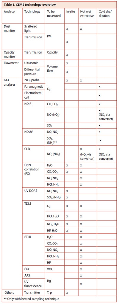
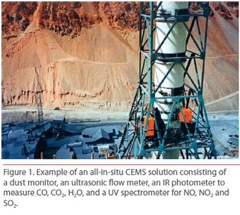
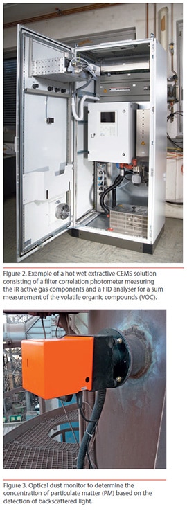
As can be seen from the CEMS technology overview in Table 1, a CEMS solutions will always’ consist of a combination of technologies in order to cover all monitoring requirements. Here, some technologies can cover a certain number of components and some specific components, like VOC, are directly linked to only one analyser technology – flame ionisation detection (FID) in this case. Besides the technology mix, the measuring approach can also differ. Many parameters can be measured in-situ, directly in the stack. The in-situ approach is favourable in general, as the sample extraction and conditioning is the source of most operational problems and maintenance requirements. However, with an increasing number of monitored components, the analyser hardware package needed to establish an all-in-site CEMS solution can be quite bulky and will require multiple openings in the stack. If more than a certain number of gases are to be measured, an extractive multi-component technology may then be considered the better choice.
together with the corresponding emission limit values or requested measuring ranges. For reference and scaling purposes, the temperature and pressure of the flue gas, as well as the oxygen content, must be monitored at most stacks. Often, the moisture content must also be measured in the flue gas, e.g. in order to make calculate dry gas concentration values from wet gas measurements and vice versa. Determining the amount of dust particles in the off-gas is also often required; here, the monitoring requirement can differ. Sometimes it is enough to determine the flue gas opacity as an indicator of its dust load. Other times, the determination of dust concentration values in terms of mg/m3 or the calculation of a total mass flow in terms of g/h might be required. In case mass flow figures are required for the gaseous or particulate emissions, the volume flow in the stack must also be measured continuously.
For various reasons, the monitoring requirements for the gaseous compounds of an individual plan can differ significantly. For some sites, it may be enough to measure the major flue gas components (O2, CO2, CO and NO), bu other sites may also require the measurement of SO2 and unburned hydrocarbons as the sum of volatile organic compounds (VOC). It is likely that the use of alternative fuels will have a direct impact on the minimum number of gaseous compounds to be monitored continuously. Hence the total number of gaseous components to be monitored by a CEMS may range from fewer than 5 to more than 15.
As can be seen from the CEMS technology overview in Table 1, a CEMS solutions will always’ consist of a combination of technologies in order to cover all monitoring requirements. Here, some technologies can cover a certain number of components and some specific components, like VOC, are directly linked to only one analyser technology – flame ionisation detection (FID) in this case. Besides the technology mix, the measuring approach can also differ. Many parameters can be measured in-situ, directly in the stack. The in-situ approach is favourable in general, as the sample extraction and conditioning is the source of most operational problems and maintenance requirements. However, with an increasing number of monitored components, the analyser hardware package needed to establish an all-in-site CEMS solution can be quite bulky and will require multiple openings in the stack. If more than a certain number of gases are to be measured, an extractive multi-component technology may then be considered the better choice.
Step 2
Find out whether the CEMS Solution needs to comply with certain national and/or international rules and standards
Normally, the reporting rules are derived from national regulations or taken from internationally established rules and standard like those existing in the European
Community or those given by the US Environmental Protection Agency (EPA). Certain CEMS technologies might not comply with the local regulations valid for an individual site. Additionally, some potential suppliers may not meet the necessary preconditions to fulfil the regional requirements in these regulated markets, e.g. a working quality management system required in the European Community. The compliance of the chosen CEMS is the responsibility of the plant operator. Hence, the legal requirements for the CEMS must be known and covered by the chosen CEMS system and its supplier. The degree of freedom for a CEMS solution may be limited by the regulatory requirements. In any case, an appropriate supplier should be able to find a solution which is the most cost-effective under the given operational and situative conditions.
Step 3
Check whether there is any new regulation coming in the foreseeable future that may have an impact on emission permits and reporting rules.
Environmental legislation is not a static, but follows a global trend towards an increasingly more sustainable and environmentally friendly technical standards, whenever available at affordable costs. Consequently, the emission monitoring requirements may increase over time. As a prominent example, the EPA has recently announced a new maximum achievable control technology (MACT) rule for cement plants, requiring the additional monitoring of hydrochloric acid (HCI) and mercury (Hg). If additional components must be measured and reported, or the emission limits of a measured component change, the suitability of the existing CEMS must be checked and matched accordingly. In this situation, multi-component systems covering many gaseous components offer the opportunity to upgrade to additional components at low costs, whereas multi-technology solutions allow for the exchange of an individual analyser when the formerly chosen one is no longer suitable. In general, the chosen CEMS solution should offer some degree of freedom in order to be adapted to future requirements.
In case mercury emission values need to be monitored continuously, the very low measuring ranges (in the low microgram region) require a separate stand-alone and state-of-the-art analyser technology specifically for this component. Recent developments indicate that even measuring ranges below 10 micrograms can now be met at affordable system costs and operational efforts.
Step 4
Clarify the operational conditions of your CEMS: what fuel is the kiln currently using? Might the fuel be changed in the foreseeable future?
Alternative fuels normally have less influence on the emission values when the kiln proves situations where it can be challenge for a CEMS because of considerable amounts of aggressive gas compounds that demand special care and treatment if they are not to have a negative impact on the measurement performance and/or lifetime of a CEMS. In-situ devices and hot wet sampling systems have shown a good lifetime cost performance even in the presence of high amounts of aggressive gas compounds such as condensates or aerosols, which are intrinsically avoided at any wetted part of the analyser system. In general, cold dry sampling systems can also be designed to operate under these conditions, but on the price of additional filter steps with high maintenance requirements and at elevated operational risk since the sampling and conditioning system must protect the analyser equipment from fouling at any time.
The choice of fuel also has an impact on the regulatory requirements. Those plants using fossil fuels are only considered as comparable to power utilities having moderate monitoring requirement, whereas the use of alternative fuels can require the plant to refer to the emission rules of waste incineration plants, which have significantly higher monitoring requirements. In case the latter use of alternative fuels is intended, the CEMS should also be able to cover future increasing operational and regulatory demands.
Step 5
Identify whether the raw material is a source of critical gas components such as organic compounds, ammonia, chorine, sulfur, etc.
These gas components are known to be critical for analyser systems, especially in connection with cold extractive sampling. The design of the CEMS sampling system must consider expected high concentrations of these gas compounds. Again, in-situ and hot wet sampling solutions are known to be much less sensitive to these aggressive and tricky-to-handle components than cold dry sampling approaches.
Step 6
Verify whether the operational conditions of the CEMS will stay constant over tis lifetime
Gas cleaning steps, like DeNOx or wet scrubbers, will decrease the amount of pollutants significantly and may require much lower measuring ranges for the monitored gases when in operation. The related analyser technology in the CEMS should be able to be adapted to lower measuring ranges.
Additionally, the temperature and moisture level in the flue gas stack may change, which can have an impact on the suitability and performance of the CEMS. Process additives like ammonia or urea introduced in a SNCR DeNOx plant can result in considerably higher NH3 concentrations in the flue gas. This can result in a lower availability and higher lifetime cost of the CEMS, as mentioned earlier.
Step 7
Take the lifetime costs for your CEMS into account and not just the initial investment
The lifetime of a CEMS is typically well over 10 years of continuous operation. Depending on the chosen measuring approach, in-situ, dilution, cold dry or hot wet sampling, and the analyser technology mix, the lifetime cost can be more than three times higher than the investment taken initially. Hence it definitely makes sense to consider a total lifetime cost scenario for a CEMS system instead of just comparing the initial system prices. Although often higher in price, all-in-situ CEMS systems offer the best performance in terms of lifetime cost as they do not require costly maintenance in the gas sampling and conditioning system.
Additionally, in-situ analyser technology is meant to work under harsh environmental and operational conditions, which leads to robust and stable product designs.
In general, it can be stated that it is not the analysers, but the sampling and conditioning systems that are the main sources for operational failures and maintenance requirements of a CEMS. A failure in the sampling system can cause fatal damage in the subsequent system components, such as the delicate sensor technologies of the analysers. Therefore, if an extractive approach is chosen, the simpler the set-up, the better the availability and cost performance, and the lower the operational risks. Here, the hot wet sampling approach has an intrinsic advantage over dilution and cold dry solutions.
A second considerable source of lifetime cost is the need for consumables like instrument air and/or calibration gases. Analyser technologies requiring daily span and zero check by gases will cause significantly higher lifetime costs than those working with internal validation standards. TDLS-based analysers with internal reference gas cells are known to operate over years without the need for a single calibration with the test gases. Especially in the case of delicate gas components like HF and NH3, the advantage of not needing calibration gas bottles is worth mentioning.
Step 8
Check the preconditions to operate and maintain the CEMS. Do you have enough skilled staff aboard for the chosen technical solution?
According to the European quality standard, CEMS require a field-proven availability (measurement uptime) of higher than 95%. Here, all maintenance periods and validation cycles contribute to the total downtime of the system. Extractive systems can fulfil these availability requirements, but at the cost of significantly higher maintenance efforts than in-site systems. Among the extractive systems, those systems incorporating a gas cooler to get rid of the moisture in the flue gas can be regarded as most demanding in this context. Especially in connection with water soluble and/or acid forming gas compounds in the sample, an appropriate gas conditioning becomes quite delicate. Any failure of an upstream filter step can cause fatal damage of the subsequent system components. In case a permanently available and well educated CEMS maintenance team cannot be afforded, and in-situ or hot wet extractive approach should be considered instead.
Step 9
Take the environmental and situative conditions of your site location into consideration
The environmental conditions at site must of course be considered in the system approach. A solution meant to work north of the Arctic Circle will definitely look different to a system designed for the Arabian Dessert.
Cement plants are often located closed to the sources of raw materials or close to huge construction areas, e.g. dams requiring a large amount of concrete. As those places can be quite remote, the availability of spare parts and the logistics of consumables should be a topic to consider as well. Some CEMS are asking regularly, sometimes even daily, for validation with the bottled test gases. Some of these gases like NH3 and HF are expensive and delicate to handle as they have limited lifetimes, or are corrosive, toxic, etc.
The capability of a supplier to do system diagnostics remotely via a data link either by a phone line, GPRS, or internet can be a big advantage for remotely located sites. Simple system failures can be identified easily and, in case a field service technician visit is still needed, the technician can bring the proper spare parts. Remote diagnostics can avoid unneeded field service and this save time and money.
Step 10
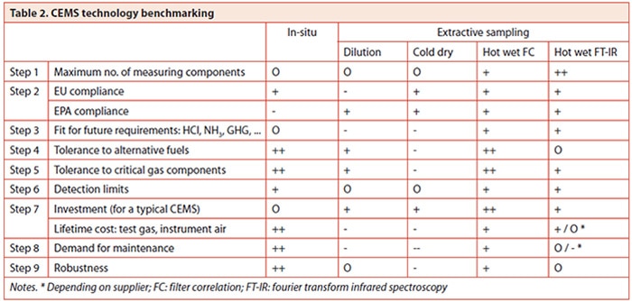
Benchmark the capability of a potential supplier for all your major requirements.
As explained over the last nine steps, the choice of a CEMS is a complex process. Multiple preconditions at the individual installation site must be considered in detail. Table 2 summarises the most important decision steps and indicates the general suitability of a certain CEMS approach. Consequently, the CEMS supplier should be able to follow and support the decision process in order to be able to offer an appropriate customer specific solution. A wide range of CEMS competence and analyser technology coverage, a sound regulatory knowledge and an available solution portfolio for the specific demands of the cement industry are indicators that the particular supplier is the right partner to talk to. The offered CEMS design should be ruled by the specific requirements of a site instead of the preferred limited technology approach of a particular supplier. The availability of field service and spare parts is also a point to be considered; therefore the supplier should also have a sufficient support structure in place.
(Reprinted from worldcement.com)