Rotary encoders, also called motion control sensors are used to measure lengths, positions, revolutions or angles. They convert mechanical movements into electrical signals. The functional principles are divided into incremental and absolute encoders.
Motion Control Sensors
Oct 4, 2022
Incremental and absolute encoders
Incremental encoders generate a fixed number of discrete (digital) impulses per revolution of the encoder shaft. The position is determined by the number of pulses which correspond to a well-known and fixed mechanical motion. The determination of speed takes place via the number of impulses per time unit and typically, the counting is done by a separate counter, regulator or PLC (Programmable logic controller). The positioning feedback of a single turn encoder is always 0 after exactly one full revolution.
The output of absolute encoders is a clear and absolute value of the position of the encoder shaft. Therefore, the position of the shaft is always known and it can be provided during power-on. With absolute encoders, a differentiation is made between singleturn and multiturn. While singleturn encoders track the position within a single revolution of the encoder shaft, the multiturn encoders count the number of revolutions. That means, multiturn encoders generate an absolute singleturn and multiturn position. The number of revolutions of multiturn encoders changes to 0 when the number of revolution exceeds a limiting value (which is usually 4,096 revolutions 0 … 4,096). To detect the number of revolutions an additional gear is necessary for multiturn encoders. In case of the multiturn, there are optical and magnetic encoders.
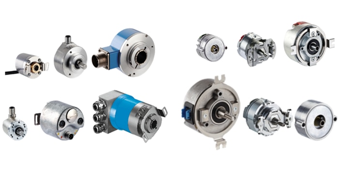
Differences in mechanical design: shaft version vs. hollow shaft version
The use of hollow shaft encoders saves up to 30 % costs and up to 50 % installation space compared to shaft versions. This is possible because additional clutches, assembly devices and other fixing components are not necessary. Hollow shaft encoders are simply assembled by pushing or sticking it onto the drive shaft and – in the easiest case – secured against rotation by a cylindrical pin. In addition, hollow shaft encoders generally require a smaller installation depth.
Motor feedback systems
A distinction is made between motor feedback systems and standalone encoders. Nevertheless, the systems work with similar function principles. Based on the performance level of the device, we distinguish between magnetic and optical technologies.
An encoder is typically assembled directly on the machine. The signal is sent directly to a PLC, either as an incremental signal or via serial communication (such SSI or industrial ethernet). In contrast to this, motor feedback systems are typically assembled directly on the motor as part of the motor construction and like a motor component. The position feedback is transmitted to the motor drive via HIPERFACE® or HIPERFACE DSL®. This means, motor feedback systems are the ideal solution for commutation, position determination and revolution measurement of electric motors. Due to excellent temperature resistance, high resolution, high stability and compact design, short motor lengths are no problem for our wide product range. Motor feedback systems operate almost exclusively on the absolute value principle and are available as singleturn and multiturn.

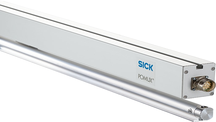
Linear Encoders
In addition to rotary encoders and motor feedback systems, SICK also offers systems for linear movements. Here, measurements are based on the principle of magnetostriction, which is similar to the time of flight (ToF) principle, and the magnetic principle.
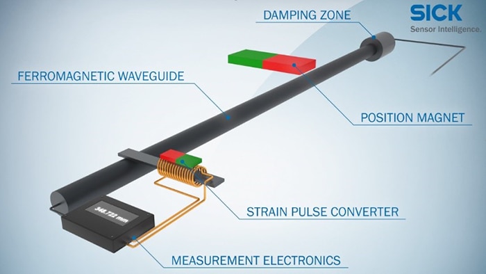
Magnetostrictive operating principle
Due to the magnetostrictive operation principle a pulse is generated and transmitted to the waveguide. Parallel to the pulse a timekeeping starts. The pulse creates a radial magnetic field which passes through the waveguide. When the pulse passes the position magnet, which is connected to the movable machine part, the magnetic fields interact and generate an ultrasonic wave that spread through the waveguide. The wave extends to the whole length of the waveguide and is converted into an electrical signal by the pickup coil. This signal stops the timekeeping. The measured time is transferred into a linear position determination system.
Linear encoders or linear motor feedback systems with a magnetic operating principle consist of a reading head and several measuring standards. The measuring standards are passive magnets that generate a magnetic field, which, in turn, is detected by the reading head. The changes in the magnetic field within the measuring standards contain information about the absolute position of the reading head, which is mounted on the movable machine part.
A special form of magnetic measuring standards is the magnetic tape with a magnetic code pattern. Like optical absolute encoders, the magnetic tape has an incremental (sin/cos) and an absolute track. The reading head continuously records the pattern using echo sensors to detect the absolute position.
Application examples
Incremental encoders are suitable for measuring speed and position in numerous applications such as a vertical form, filling and sealing machine. These machines typically have an important motion-related feature: the length of the bag, which has to be monitored. Using an encoder, mounted on the unwind mechanism, and a contrast sensor as a trigger, the length of the bags can be measured and monitored.

Absolute encoders are used to measure the absolute position in various industries, machines and work equipment, e.g. in automated guided vehicles (AGVs). To record the current steering angle of the AGV, the steering angle drive is equipped with an AHS/AHM36 absolute encoder. It provides data for determining the steering angle, which, in addition to other parameters such as speed, lift height, load pickup position and load weight, can be used to monitor vehicle stability.

Linear encoders are used to monitor a linear motion, e.g. when positioning a SCARA robot (Selective Compliance Assembly Robot Arm) on a linear axis. The SCARA robot must move synchronously with the conveyor belt speed, so it can take workpieces from the conveyor belt. The TTK70 linear encoder determines the absolute position of the SCARA robot. The encoder consists of a compact reading head and a magnetic tape as a reference scale. The contactless operating principle ensures wear-free determination of the position. Using a unique code pattern, the encoder records the information about the absolute position along the reference scale and transmits it directly to the evaluation electronics. After installation, the system is immediately available and completely maintenance-free, which saves time and costs.